The sterilization of pharmaceutical products, materials and medical devices must consider the potential impact of the process on the materials being processed, which can play an important role in the selection of an appropriate process.
Vapor sterilization can be a useful process for heat-labile materials and equipment. In less critical applications, such as rooms and enclosures, decontamination using similar systems can be useful to control microbial populations.
An important aspect of vapor treatments is the presence of two phases, gas and liquid. This duality presents unique challenges that must be appropriately considered for success. When there is only a small amount of liquid present, a vapor can appear to be a gas, whereas at higher concentrations the liquid phase may condense on surfaces and become increasingly visible.
Vapors used for sterilization and decontamination are produced by either of these two procedures:
- Heating aqueous solutions of the chemical agent above the boiling point to where the agent and water are both gases, dispersing that mixture into a hot air stream and introducing the heated gas combination to the target system
- Introduction of purified compressed air as a carrier for the sterilant liquid to disperse it into a small fog droplet that is usually less the 10 microns in size.
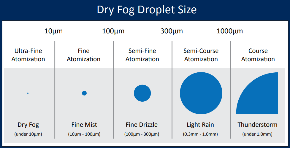
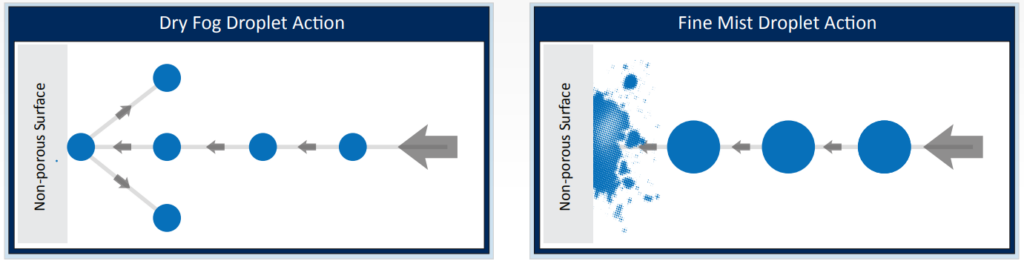
The size of the particles affect its dispersion and bouncing of the hard surface thus avoid excessive condensation, corrosion and surface wetting issues associated with a fine mist bio-decontamination procedure , as following:
The most commonly utilized agent is Hydrogen peroxide although other materials such as peracetic acid or formaldehyde can also be utilized.
Popular Supplier for Cold Sterilant liquid are:
- Minncare
- Renalin
- Peracedin
- Micro-X
A concentration of 3% of H2O2 can achieve 106 Complete kill of bacterial population (Geobacillus stearothermophilus) upon exposure for 150 minutes.
Placement and operation of the fogging machine shall be according to the manufacturing manual.
# Calculation of the Dry Fogging process:
- To be able to calculate the amount of sterilant and pure water needed to achieve an effective sterilization of a definite area there are 7 factors that must be measured:
- Total Area Volume
- Average Relative humidity
- Average Temperature
- Volume of sterilant required per m3
- Residual Volume of the Dry Fog Machine (ml)
- Number of Nozzles of the Dry Fog Machine
- Specific Room Adjustment Coefficient (Grams of Water/m³)
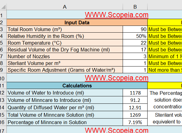
- By determining the pervious data you can use the attached Excel sheet to calculate the following :
- Quantity of Diffused Water per m³ (ml)
- Percentage of sterilant liquid in solution
- Volume of water to introduce
- Volume of sterilant to introduce
- Total Volume of used solution is the sum of water and sterilant introduced volume
- Download link: SCOPEIA Dry fog Excel Sheet Calculation
Procedure of water test to determine the room coefficient:
- Install the Dry Fog System inside the area to be tested and position it.
- Install the Relative Humidity (RH) sensor(s) at selected location(s) and measure the initial Relative Humidity.
- Using the Dry Fog Calculation spreadsheet enter the volume of the area (m³), initial RH (%), initial T° (°C), residual volume (mL), number of nozzle(s) used, volume of Sterilant used per cubic meter (simulation) and set “0” as Specific Room Coefficient.
- Note the calculated Total Volume (water + Sterilant) considering the initial parameters above and add x% more (x has to be decided about 30-40 or 50%)
- Put the total quantity of water (calculated + additional quantity) inside the Dry Fog vessel and note the exact quantity of water used. Prepare the machine and the room for fogging: connect the machine to the compressed air source, clean the nozzle(s), seal off potential air leakages, set the air pressures on the machine, seal the external doors from outside, turn OFF the HVAC.
- Switch ON compressed air source and start fogging with water. 2-3 people maximum can stay inside (only when running with water) the room to control the fogging as well as checking for potential areas of re-condensation. Their location shouldn’t interfere with the mist dispersion. Control and record the relative humidity from the different sensors used inside the area every few minutes.
- Switch OFF compressed air when the average RH is about 75%. Wait additional 20 minutes after the system stops for controlling the RH is reasonably stable; it will correspond to a short contact time simulation.
- After the contact time simulation, turn ON the HVAC to vent the room. RH recording is recommended to evaluate the time needed to vent the room.
- Go back to the machine and drain the vessel. Measure the volume left and making the difference with the initial volume, to calculate the volume of water sprayed out by the system.
- Using the Dry Fog Calculation spreadsheet, modify the Specific Room Adjustment coefficient (in + or -) for getting the amount correct, Total Volume box, a calculated volume corresponding to the actual volume of water sprayed during your water test. When you get that volume showed by modifying the Room Coefficient you automatically have defined the corresponding coefficient. That coefficient can be used every time you need to calculate the amount of water and Sterilant needed to disinfect that specific area.
Example:
| Initial parameters | Calculated Volumes | Result |
| Room Volume: 350 m³ Initial RH: 35% Initial Temperature: 21°C Residual Volume: 30 mL Number of nozzles: 3 Sterilant volume per m³: 1.5 mL Specific Room Coefficient: 0 |
Volume of water: 5451 mL Volume of Sterilant: 528 mL Total volume: 5979 mL |
Volume of water inside the vessel for the water test: 9000 mL (5979 + about 50%) Residual volume left inside the vessel after fogging: 2250 mL Volume actually used for the water test: 6750 mL Entering +2.2 in the Room Coefficient box the total volume calculated becomes 6749 mL The Specific Room Coefficient for that specific room/area is + 2.2 |
Accurate determination of the D-value requires precise measurement of the lethal conditions to which the microorganism is exposed, and these must be reported with the D-value. D-values for gases and liquids are easily developed as the agent concentration, RH and temperature can be accurately measured.
Accurate determination of the D-value does not apply to vapors where the conditions at the point of kill are unknown. D-values for vapor sterilization processes are indeterminate, as the sterilizing conditions (phase, concentration, humidity level) to which the microorganism are exposed are unknown.
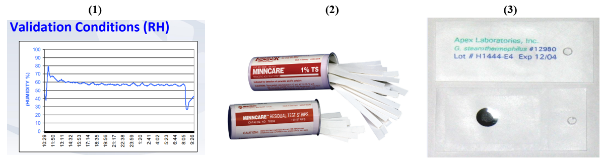
There are 3 indicators that can be used to assure an effective sterilization to some degree
- Physical indication: Humidity in the room after fog operation of value more than +30% of initial humidity can indicate the distribution of the solution to all locations.
- Chemical indicator: Validated Acid Test Strips provide quick results with easy-to-read indication of 1% concentration of sterilant after dilution.
- Biological indicator (Geobacillus stearothermophilus): No growth rate after incubation indicates an effective 6 log reduction of the bacterial population.
#Validation of Vapor Sterilization
The performance qualification or “Validation” activity has been described as documentation that the process or product conforms to expectations as determined through independent parameter measurement and/or intensive sampling or challenge.
It is common practice in performance qualification to utilize a “worst-case” challenge in sterilization/decontamination processes
Typical “worst-case” challenges for vapor processes include: reducing cycle dwell time, reduction of agent concentration and the use of resistant biological challenges as bioburden surrogates.
There are two methods to validate the gas sterilization process which are “half-cycle” approach and “bracketing” approach.
Half Cycle Validation: which mandates a sterilization dwell period that destroys not less than 106 spores of a resistant biological indicator.
Use of the “half-cycle” method provides overkill: “Overkill sterilization can be defined as a method in which the destruction of a high concentration of a resistant microorganism supports the destruction of reasonably anticipated bioburden present in routine processing”.
In routine operation, the process dwell period is doubled.
Bracketing Validation: which better supports the extremes of the operating ranges for the critical process parameters.
In the bracketing approach there are two cycles:
- a minimum cycle with lower concentration, lower RH and a shorter dwell period is confirmed by BI destruction using what are understood as less lethal conditions.
- a cycle employing a higher concentration, higher RH and a longer dwell period where the adverse impact is believed to be greater and material effects are evaluated
Routine operation of the system utilizes conditions that fall between the process extremes that have been evaluated.
The routine cycle duration using the bracketing approach is typically not double the duration of the complete kill end point, and this allows for a shorter overall routine cycle duration.
Regardless of the validation approach, the use of multiple biological indicators at all locations can add greater confidence in the process’ robustness. Because the lethal conditions differ across the system, the locations overall are not replicates, which is only possible with multiple biological indicators at individual locations.